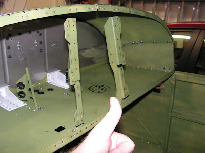
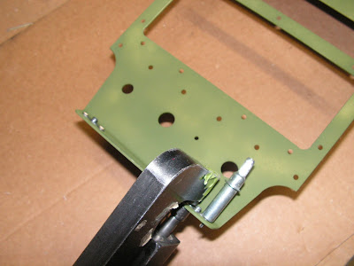
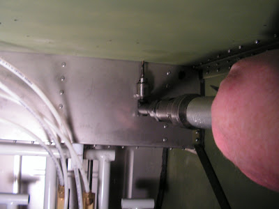
Today's entry will all but finish the forward upper fuselage on the RV12 aircraft. All that will be left is the final mounting of the instrument panel. One comical thing is I realized I riveted the comm radio stack supports in transposed! Below is pictured the wrong way followed by the corrected installation.

Reference: 29A-08
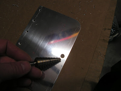
Step 1: Remove the excess material from the Map Door. Machine countersink all #40 holes in the map box door to fit the head of an AD3- flush rivet. Deburr all holes and edges.

Chamfer the 1/4 inch hole in the map box door with a drill bit by hand so the Camloc Fastener fits flush against the Map Box Door.
Step 2: Machine countersink all #40 holes in the SkyView Inst Panel Right to fit a AD3- flush rivet. Machine countersink all .1444 holes in the SkyView inst panel right to fit the head of an AN507C632R8 screw. Builder's note: I used a #27 100 degree countersink.

Step 3: Deburr all holes in the Map Box Hinges.
Step 4: Separate the two Map Box halves and deburr all holes.
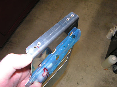
Step 5: Rivet the Map Box Hinge to the Map Box Door.

Step 6: Blind rivet the two Map Box Halves together.

Step 7: Rivet and blind rivet the Map Box Assembly to the SkyView Inst Panel Right. Rivet the Caloc Receptacle to the Inst Panel Right Assembly.

Step 8: Blind rivet the Map Box Hinge to the lower Map Box Half.


Reference: page 29A-09
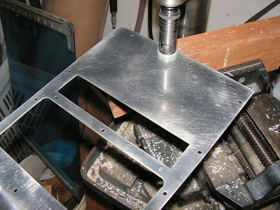
Step 1: Remove the hatch areas from the the Skyview Reinf Angle as shown in figure 2 of the RV12 plans page 29A-09.
Attach the SkyView reinf angle to the Inst Panel Left using the hardware called out.

Step 2: Attach the remaining hardware to the SV1000 Inst Panel Left. The rivet holes for the nut plates need to be countersunk before doing this.
Machine countersink the screw holes for a AN507C632R8 screw.

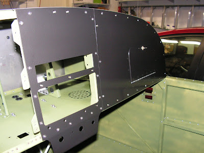
Builder's note: The screw holes that are used for mounting the SkyView screen are not countersunk. See picture below:


Step 3: Rivet two nutplates to the bottom of the SV Center Lnst Panel SL-40.
Machine countersink the screw holes in the SV Center Inst panel.
Now is the time to paint or otherwise finish the instrument panel. I used a flat black primer and then top coated with Rustoleum Hammer tone paint.
Reference 29A-10
Step 1: Install the SV Cent Inst Panel with the hardware called out on page 29A-10 of the RV12 plans by Van's Aircraft.

Step 2; Install the Map Box Assembly to the Panel Base>
Match-drill #19 through the holes into the Panel Base. See figure 2 page 29A-10.
Step 3: Remove the Map Box Assembly and deburr holes.

This completes the Forward Upper Fuselage section with the exception of the final mounting of the instrument panel.

